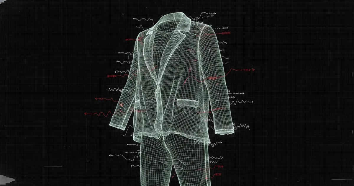
Mapping physical textile properties to simulation solvers is the bridge between a visual approximation and a production-ready digital twin. In high-fidelity cloth simulation, the goal is to translate measurable mechanical data—such as Young’s Modulus, shear modulus, and mass density—into the numeric constraints that drive Position-Based Dynamics (PBD) or Extended Position-Based Dynamics (XPBD) solvers. This process ensures that a digital drape accurately reflects the behavior of its physical counterpart under gravity, collision, and motion.
Key takeaways
- PBD solvers prioritize stability by manipulating particle positions directly to satisfy distance and angle constraints derived from physical material tests.
- Tensile and shear stiffness map to distance constraints between mesh vertices, while bending stiffness is governed by dihedral angle constraints between adjacent triangles.
- Accurate mass density (g/m²) is the critical scalar for calculating particle mass, which dictates the momentum, inertia, and gravitational response of the simulated fabric.
- Material digitisation platforms like Seddi Textura automate the capture of these parameters, converting optical and mechanical scans into solver-ready presets.
- High-performance apparel simulation requires non-linear physics mapping to account for the complex, anisotropic behavior of technical textiles.
What are the primary physical properties required for cloth simulation?
To simulate fabric, you must first define its mechanical identity. Fabric is not a continuous medium but a complex structure of fibers and yarns that exhibit anisotropic behavior—meaning it reacts differently depending on the direction of the force (warp vs. weft). The four primary pillars of fabric physics are tensile stiffness, shear stiffness, bending stiffness, and density.
Tensile stiffness (stretch) measures the resistance of the fabric to elongation along the grain lines. Shear stiffness measures the resistance to in-plane deformation, specifically how the warp and weft yarns slide against each other when the fabric is pulled on the bias. Bending stiffness defines the fabric's resistance to curvature, which determines the size and shape of the folds in a drape. Finally, density—usually measured as mass per unit area—determines how heavy the fabric feels and how much force is required to move it.
In professional environments, these parameters are often derived from standardized tests like the Kawabata Evaluation System (KES-F) or the FAST (Fabric Assurance by Simple Testing) system. These tests provide the raw data that must be mapped to the specific inputs of a 3D solver.
How does a Position-Based Dynamics (PBD) solver process these inputs?
Most modern interactive 3D tools, including Marvelous Designer, utilize Position-Based Dynamics (PBD). Unlike traditional force-based solvers that solve for acceleration using Newton’s Second Law ($F=ma$), PBD solvers work by directly manipulating the positions of vertices (particles) to satisfy a set of constraints. This approach is significantly more stable for real-time applications and allows for larger time steps without the simulation "exploding."
When you input a stiffness value into a PBD solver, you are essentially defining the "strength" of a constraint. For every simulation step, the solver predicts the new position of each particle based on its current velocity and external forces like gravity. It then runs an iterative loop to project these particles back to positions that satisfy the constraints. If a distance constraint (representing stretch) is violated because two particles have moved too far apart, the solver pulls them back together. The stiffness parameter determines how much of that correction is applied in a single iteration.
How do you map tensile and shear stiffness to distance constraints?
In a triangular or quadrangular mesh, tensile stiffness is mapped to distance constraints along the edges of the polygons. For a fabric simulation to be accurate, the solver must distinguish between the warp (longitudinal) and weft (transverse) directions. This is achieved by aligning the mesh edges with the UV coordinates of the pattern.
Shear stiffness is more complex because it represents a change in the internal angle of the fabric weave. In a PBD solver, shear is often mapped to diagonal distance constraints across a quad or between non-adjacent vertices in a triangle fan. If the shear stiffness is low, the solver allows these diagonal distances to change more freely, resulting in the characteristic "bias stretch" seen in lightweight silks or knits.
As professional athletes like Jessica Pegula noted on August 17, 2026, the physical properties of a kit—from how it grounds the wearer to its technical performance—are critical, making the digital simulation of such high-performance textiles a matter of engineering rather than just aesthetics. For brands like Arc'teryx, mapping these tensile and shear parameters correctly is the difference between a jacket that looks like Gore-Tex and one that behaves like it in a technical environment.
Why is bending stiffness the most difficult parameter to simulate?
Bending stiffness is a "weak" force compared to tensile stiffness, but it is the primary driver of visual fidelity. In a discrete mesh, bending is typically modeled using a dihedral angle constraint. This constraint evaluates the angle between two adjacent triangles that share a common edge.
If the fabric is stiff (like a heavy denim), the solver applies a strong correction to maintain the rest angle (usually 180 degrees). If the fabric is drape-heavy (like a jersey), the solver allows the angle to change significantly. The difficulty arises because real fabric bending is non-linear and depends on the thickness of the material. Furthermore, bending resistance in textiles often exhibits hysteresis, meaning the fabric doesn't return perfectly to its original shape after being folded. Most PBD solvers approximate this with a linear stiffness coefficient, though advanced research from NVIDIA Research continues to push into more complex, non-linear bending models that better capture the "break" of heavy fabrics.
How does Marvelous Designer 2025.1 handle fabric physics?
Marvelous Designer, which is owned by CLO Virtual Fashion, remains a standard for pattern-based simulation. The latest release, version 2025.1, introduced on August 17, 2026, has expanded its physics capabilities to include softbody simulation, which is useful for simulating the interaction between garments and soft tissue or padded components.
In the Marvelous Designer environment, physics parameters are categorized into "Fabric Property" presets. These presets map physical units to internal solver weights. The software's new Pattern Drafter and AI Pose Generator (beta) rely on these underlying physics to ensure that as an avatar moves, the fabric responds realistically. For engineers, the challenge is that these internal weights are not always 1:1 with SI units. Users often have to use a "Fabric Emulator" or material kit to calibrate the digital material against a physical sample to find the correct mapping for bending, stretch, and shear.
What is the role of cloud-based material capture in Seddi Textura?
For many enterprises, the manual entry of physics parameters is a bottleneck. Seddi addresses this through its Textura.ai platform, which provides a cloud-based infrastructure for generating 3D digital textiles. Instead of manually guessing stiffness values, Textura uses a combination of optical scanning and mechanical data to create a digital twin of the fabric.
This data is then piped into Seddi Decorator™, a workspace for branded apparel that ensures artwork placement and drape are true-to-pattern. By automating the extraction of physics parameters, Seddi removes the subjectivity of "vibe-based" simulation. In simulation, relying on visual "vibes" rather than hard physics parameters is a common pitfall; as noted in discussions regarding software development, if everyone just vibe coded their own tools without rigorous underlying logic, the resulting systems lack the stability required for production environments. Seddi’s approach ensures that the numeric inputs for the solver are grounded in empirical measurement.
How do solver iterations and mesh density affect accuracy?
The accuracy of a simulation is not just a function of the input parameters; it is also highly dependent on the solver configuration. In PBD, the "stiffness" of a constraint is effectively coupled with the number of solver iterations and the simulation time step. If you increase the number of iterations, the fabric will appear stiffer even if the input parameter remains the same.
Mesh density also plays a critical role. A finer mesh (more vertices) allows for more detailed folds but requires more iterations to maintain the same level of global stiffness. This is known as "locking." If the mesh is too coarse, the fabric will look like paper; if it is too fine without enough solver iterations, it will look like wet silk regardless of the physics settings. Engineers must balance these variables to achieve a stable, realistic result.
Comparison of Fabric Physics Mapping
| Parameter | Solver Input Mapping | Physical Unit | Best For |
|---|---|---|---|
| Tensile Stiffness | Distance Constraint | N/m (Newton/meter) | Controlling garment growth and fit accuracy. |
| Shear Modulus | Diagonal/Area Constraint | N/m | Simulating bias-cut drape and knit skewing. |
| Bending Stiffness | Dihedral Angle Constraint | Nm (Newton-meters) | Defining fold scale and wrinkle density. |
| Mass Density | Vertex/Particle Mass | g/m² | Gravitational drape and inertial movement. |
| Friction | Coulomb Friction Coeff. | Dimensionless | Multi-layer interaction and garment stability. |
What are the common failure modes in fabric physics mapping?
The most frequent failure in fabric simulation is the "stretchy" look, where a garment appears to be made of rubber. This usually happens when the tensile stiffness is too low or the solver iterations are insufficient to satisfy the distance constraints. Another common issue is "interpenetration," where layers of fabric pass through each other or the avatar. This is often caused by a mismatch between the fabric thickness parameter and the collision detection distance.
Sander Lak, who is currently three collections deep into his genderless venture Sanderlak, is scheduled for a reshowing of his latest collection on August 17, 2026, highlighting the industry's continued reliance on precise garment construction even as labels evolve. For designers like Lak, the digital simulation must handle complex layering and high-end fabrications without these failure modes to be useful in a professional workflow.
FAQ
How do I convert Kawabata (KES-F) data to Marvelous Designer inputs? KES-F provides values in gf·cm²/cm for bending and % strain for tensile. Most solvers require a conversion to internal stiffness weights (0-100). This usually requires a calibration step where a digital 10cm x 10cm swatch is subjected to the same virtual load as the physical test to match the displacement.
What is the difference between PBD and XPBD? Standard PBD couples stiffness with the time step and iteration count, meaning the fabric's feel changes if you change simulation settings. Extended PBD (XPBD) decouples these, allowing for stiffness parameters that are physically meaningful and independent of the solver’s frame rate or iteration depth.
Why does my fabric explode when I increase stiffness? In force-based solvers, high stiffness leads to high frequencies that the integrator cannot resolve. In PBD, "explosions" are rarer but can occur due to conflicting constraints or massive position corrections in a single step. Increasing damping or reducing the time step usually stabilizes the mesh.
Can AI predict physics parameters from a single photo? While some computer vision models can estimate "drape-ability," they cannot currently extract precise tensile or shear moduli from an image alone. Accurate simulation still requires mechanical testing or high-fidelity material digitisation from providers like Seddi.
How does mesh topology affect physics? Triangular meshes are generally more stable for complex drapes and are the standard for PBD solvers. Quadrangular meshes are preferred for certain types of deformation and UV mapping but can suffer from "shear locking" if the solver does not have specific constraints to handle quad skewing.
Conclusion
Achieving high-fidelity fabric simulation is an exercise in precision mapping. By understanding how physical units like bending stiffness and shear modulus translate into the discrete constraints of a PBD solver, engineers can move beyond visual approximations. As tools like Marvelous Designer and Seddi continue to integrate AI and automated material capture, the barrier to creating true-to-life digital twins continues to lower, provided the underlying physics remain grounded in empirical data.
Further Reading
- AI doesn't make it much easier to build security startups
- Jessica Pegula Sees Why Tennis Has Become ‘Its Own Fashion Category’
- Sander Lak Joins CFDA Calendar Ahead of NYFW